We’ll go through one of the most advanced features of Slic3r: the ability to use modifier meshes for applying distinct settings to object parts. Infact Slic3r allows users to define regions where the print settings should be overridden by distinct settings.
Some time ago I decided to design an ukulele that could be printed on a RepRap. I also called JonTom, a world-famous ukulele player for getting a review of it. You might want to enjoy the YouTube video about it.
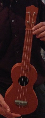
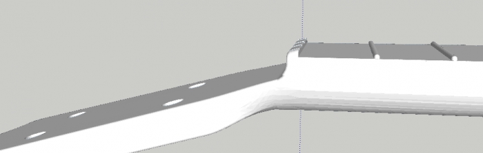
Before assembling it, I was worried that string tension would break the instrument or bend it too much. Nothing happened to the instrument body and neck. However, the head got bent a bit too much. This is how it should have been:
And this is how it turned out after tensioning strings:
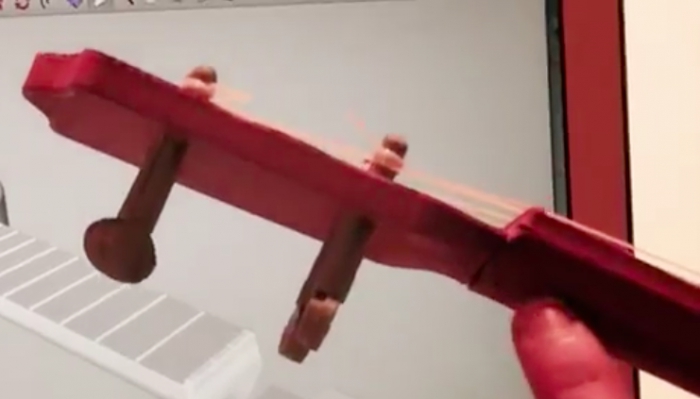
The joint I designed turned out to be too flexible:
So, at this point there would have been three possible solutions:
- redesign the parts with a larger joint (not much possible without altering the external shape of the instrument)
- print the head with 100% solid infill
- print just the joint area with 100% solid infill
I chose the third option: let’s see how this feature works.
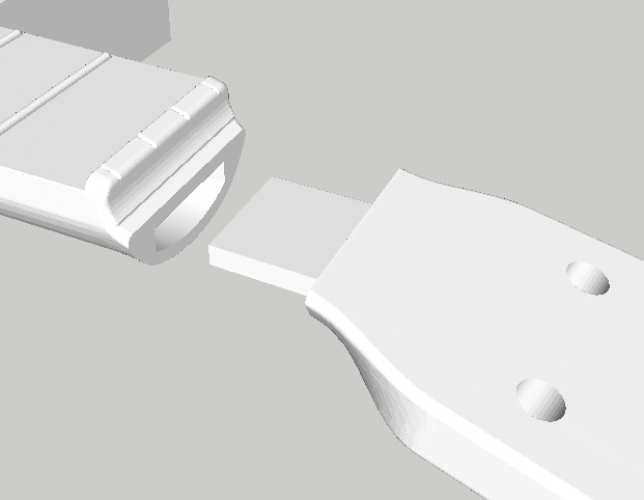
I used my CAD application to model a simple volume around the area that I wanted to print with solid infill:
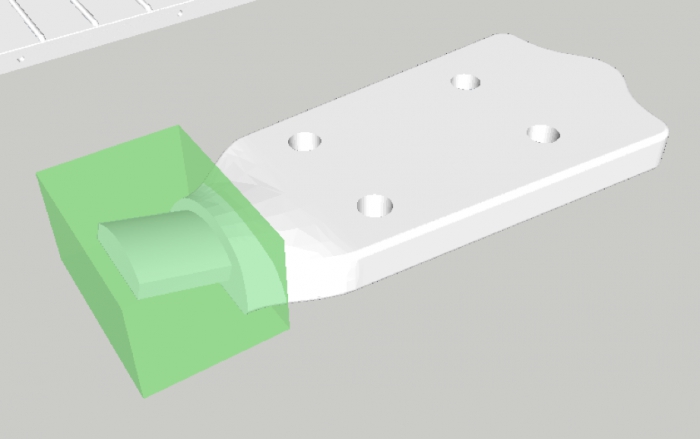
Then I exported it as a separate STL file.
Finally, I fired Slic3r up and loaded the main part, then clicked on Settings… and then hit Load modifier… I loaded the new volume as a modifier mesh and I applied 100% solid infill to it:
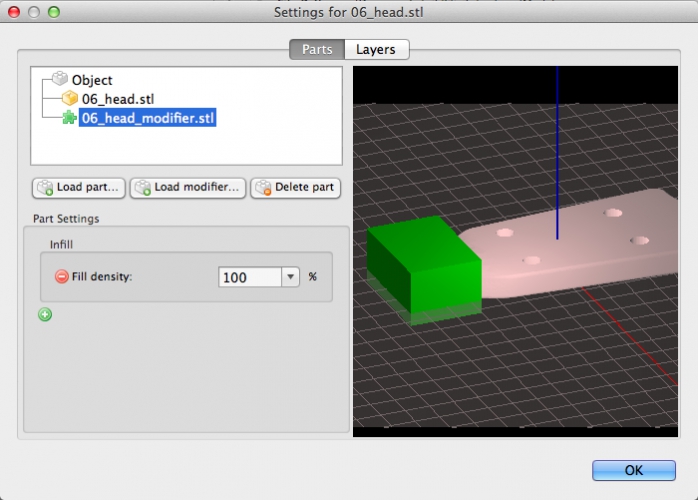
That’s it!
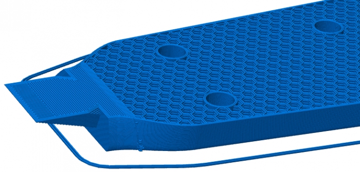
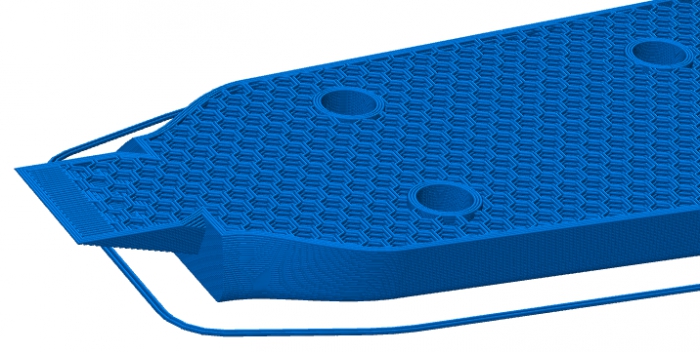
This is the comparison between a print with the modifier and without modifier. Note the solid area near the joint:
Modifiers are a different way for specifying multi-part objects: instead of importing multiple volumes that define the object shape, you can import a special volume that overlaps with the object and defines a part by subtracting it from the rest of the object.